Australian weld symbols
You can research the full range of welding symbols in the Engineering Drawing Handbook produced by Standards Australia and the Institution of Engineers.
Hey TFB firstly make sure you know what standard you are working to Hypothetically, a SAW weld from both sides should be able to achieve 18 mm depth of penetration on a 16 mm prep without backgouging so you will end up with a CJP but because it is classified as a PJP it does not require volumetric testing. Hope I have made sense, Cheers, BB. Flash, have sent a couple of e-mails to admin weldingflash. Sorry about the emails BB, technical error, I should stick to welding, I have a new machine and forgot to setup the welding flash admin account on it thanks for pointing it out R Flash. Hi Lads, The weld symbols should be to AS The rest of the drawing is complete penetration welds which leads to the confusion.
Australian weld symbols
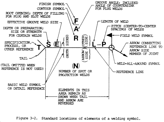
Glossary Welding symbols are used to reduce the number of words on an engineering drawing and so save space and time. Once you AS part 3 become accustomed to the symbols you will see that they help Bevelled weld you to understand exactly what needs to be done. They are universal so regardless of where you go in the Corner weld world the symbols remain the same. Double bevel weld Welding symbols can also give more information than would be possible with words. Symbols can define: Edge weld. Fillet weld joint configuration eg bevelled, butt weld or double bevel Gas metal arc welding type of weld eg fillet, lap, edge, corner, slot, or plug Joint configuration type of welding process eg gas metal arc welding, Lap weld and whether to weld on site or in the workshop. Plug weld. Slot weld Examples Welding. Welding symbols Meaning Symbol. The near or arrow side is to be welded with a single V butt weld while the other side is to be welded with a 6mm fillet weld. This is to be done on site.
See figure The weld symbol fig. Deciphering Weld Symbols Document 10 pages.
Drawing or sketching is a universal language used to convey all necessary information to the individual who will fabricate or assemble an object. Prints are also used to illustrate how various equipment is operated, maintained, repaired, or lubricated. The original drawings for prints are made either by directly drawing or tracing a drawing on a translucent tracing paper or cloth using waterproof India ink or a special pencil. The original drawing is referred to as a tracing or master copy. Reproduction Methods. Various methods of reproduction have been developed which will produce prints of different colors from the master copy. Title Block.
Material Welding. AS It provides a standardized system for indicating the type of weld, its size and location, and any other necessary information for welding on engineering drawings. The standard includes guidelines for the use of symbols on drawings and the placement of those symbols in relation to the components being welded. It is designed to be used in conjunction with other relevant standards, such as AS Technical drawing and AS The basic welding symbols used in AS These are the basic welding symbols used in AS
Australian weld symbols
Material Welding. Weld symbols are a key part of welding documentation, and understanding How to read Weld Symbols is critical for welders. There are three main elements to a weld symbol:.
Horse boarding in surprise az
Welding Symbols Document 28 pages. Richard Pohanish. Circular projection welds may be dimensioned by size. Details of Slot Welds. Hey TFB firstly make sure you know what standard you are working to Revision Block. Weld finishes contour With butt welds the welding symbol will tell you the final finish or contour, It may be ground off flush. If two parts are to be shown in one detail drawing, both prints will have the same drawing number plus a dash and an individual number such as and Full lines represent the visible edges or outlines of an object. What is Scribd? All changes to the drawing are noted in this block. The centre of the weld to the centre of the next weld is to be mm long. Here is a selection of basic symbols to learn as a first step. Welding symbols Meaning Symbol. Flush Resistance Spot Welding Joints.
Home » Welders. Engineers and welders use weld symbols during construction. During metal joining processes, weld symbols are meant to indicate different parts of the process.
This data must be shown on the drawing. The contour symbols for melt-thru welds are indicated in the same manner as that for fillet welds fig. Specific lengths of fillet welding may be indicated by symbols in conjunction with dimension lines fig. Surface Contour of Flash or Upset Welds. Each drawing has a revision block which is usually located in the upper right corner. Holes or slots in the other side member of a joint shall be indicated by placing the weld symbol on the side of the reference line away from the reader B, fig. Dimensions need not be shown on the welding symbol. Spacing of Projection Welds. Carousel Next. Resistance seam welds must be dimensioned by either size or strength as follows: 1 The size of resistance seam welds must be designated as the width of the weld expressed in fractions or in decimals in hundredths of an inch and shall be shown, with or without inch marks, to the left of the weld symbol fig. Carousel Previous.


The intelligible message