Fir matlab
Help Center Help Center.
Help Center Help Center. The frequency and amplitude characteristics of the resulting filter match those given by vectors f and a. You can use ftype with any of the previous input syntaxes. Design an FIR lowpass filter of order with a transition region between 0. Display the magnitude and phase responses of the filter. Design a differentiator of order 30 that attenuates frequencies above 0.
Fir matlab
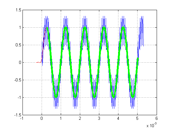
Modules include a MCU, connectivity and onboard memory, making them ideal for designing IoT products for mass production. The component database hosts libraries for different sensors, actuators, radios, inputs, middleware and IoT services. Learn about hardware support for Mbed, as well as the Mbed Enabled program, which identifies Mbed compatible products. Reference designs, schematics and board layouts to develop production hardware and Mbed-compatible development boards. Mbed 2 is now deprecated. For the latest version please see the Mbed OS documentation. Assume a lowpass filter with cutoff frequency of 6 kHz. The expectation is this should filter out the 15 kHz component from the test signal. Also align filtered signal with original and discard transient samples in this case the first order samples. Last commit 20 Nov by mbed official.
If you are not happy with the use of these cookies, please review our Cookie Policy to learn how they can be disabled. This site uses cookies to store information on fir matlab computer, fir matlab. As an example, consider designing a filter with order 61 impulse response and cutoff frequency of 0.
Help Center Help Center. The example concentrates on lowpass filters but most of the results apply to other response types as well. This example focuses on the design of digital filters rather than on their applications. If you want to learn more about digital filter applications, see Practical Introduction to Digital Filtering. Because the impulse response required to implement the ideal lowpass filter is infinitely long, it is impossible to design an ideal FIR lowpass filter.
Help Center Help Center. The frequency and amplitude characteristics of the resulting filter match those given by vectors f and a. You can use ftype with any of the previous input syntaxes. Design an FIR lowpass filter of order with a transition region between 0. Display the magnitude and phase responses of the filter. Design a differentiator of order 30 that attenuates frequencies above 0. Display the zero-phase response of the filter. Design an FIR lowpass filter. The passband ranges from DC to 0.
Fir matlab
Help Center Help Center. The example concentrates on lowpass filters but most of the results apply to other response types as well. This example focuses on the design of digital filters rather than on their applications. If you want to learn more about digital filter applications, see Practical Introduction to Digital Filtering. Because the impulse response required to implement the ideal lowpass filter is infinitely long, it is impossible to design an ideal FIR lowpass filter. These deviations are depicted in the following figure:. Practical FIR designs typically consist of filters that have a transition width and maximum passband and stopband ripples that do not exceed allowable values. In addition to those design specifications, one must select the filter order, or, equivalently, the length of the truncated impulse response. A useful metaphor for the design specifications in filter design is to think of each specification as one of the angles in the triangle shown in the figure below. The triangle is used to understand the degrees of freedom available when choosing design specifications.
Le golden wok grill photos
Main Content. For an overview of windows and their properties, see Windows. Assume a lowpass filter with cutoff frequency of 6 kHz. This may occur if the application requires a very narrow transition width or a very large stopband attenuation. The length of w is half the length of f and a , so there is exactly one weight per band. Select the China site in Chinese or English for best site performance. You can also design and implement filter in a single step using the dsp. The sample rate is Hz. The filter startup transients have finite duration. Right-clicking on the data marker displays a menu where you can move, delete or adjust the appearance of the data markers. FIR Highpass Filter. Band Amplitude Optimization Weighting [—1 —0. Search MathWorks. Call it bM.
Help Center Help Center. The frequency and amplitude characteristics of the resulting filter match those given by vectors f and a. You can use this with any of the previous input syntaxes.
A legal weight vector is always half the length of the f and a vectors; there must be exactly one weight per band. You can use ftype with any of the previous input syntaxes. Design a lowpass filter with the same specifications. The passband ripple is about times higher than the stopband ripple. Linear-phase equiripple filters are desirable because for a given order they have the smallest possible maximum deviation from the ideal filter. The "DC-0" is optional. Maximum passband deviation from 1 passband ripple of 0. In order to perform the actual filtering, call the dsp. Sidney Burrus. Both firls and firpm allow you to place more or less emphasis on minimizing the error in certain frequency bands relative to others. FIR filters are widely used because of the powerful design algorithms that exist to design such filters.


0 thoughts on “Fir matlab”