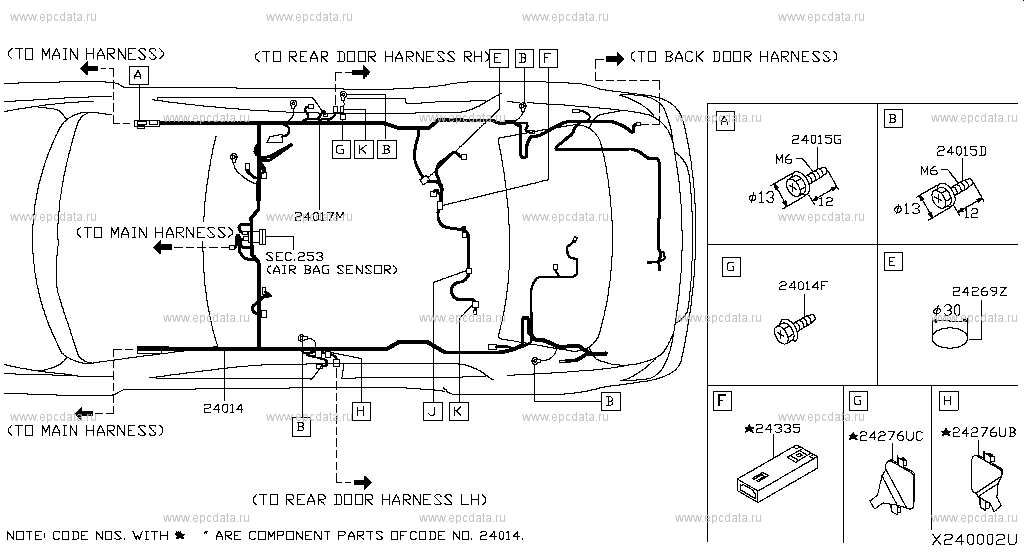
Nissan tiida wiring diagram
P ECM
Log in. Sign up. Home Forums Nissan Versa Versa. JavaScript is disabled. For a better experience, please enable JavaScript in your browser before proceeding. I have manually opened the hatch and removed the trim. The switch test OK.
Nissan tiida wiring diagram
Search your problem. Search Log in Sign up. Tiida Problems Wiring 4. Related problems:. Computer 5 Fuses 2 Sensors 9 Other problems. Top problems. My car never started again after maf wire short circuit Nissan Tiida Hatchback miles. I have a brand new battery. New spark plugs keep getting wet and over fueling. Hard start not revving and idling. Diagnostic only picks up p engine code but still no fix? Car only has 95k on clock.
Explore Our Forums. Thanks, in advance.
.
The Nissan Tiida is a mid-size sedan produced by the Japanese car manufacturer Nissan from to It is a popular vehicle due to its versatility and affordability. To keep up with this popularity, many owners need to be able to access their vehicle's wiring diagrams. These diagrams provide quick access to the information needed to diagnose and repair electrical problems with the Tiida. Nissan Tiida wiring diagrams are essential for any owner or technician who needs to repair or troubleshoot an electrical issue on the vehicle. They provide detailed diagrams showing how the different parts of the car's electrical system are connected and how they interact. This makes it possible to pinpoint the source of any problem quickly and accurately.
Nissan tiida wiring diagram
Please view this preview to check your job is included. For a new generation of vehicles, welcome to an all-new repair guide. When we first began selling manuals in the s, vehicles were simple to maintain and there were relatively few models on sale. So at Haynes, we knew that to continue offering a great product, we needed to take a brand-new approach - nothing less than a reinvention of the repair manual. With so many models on sale, it is impossible to strip down and rebuild enough cars to cover the market properly. Instead, Haynes Autofix is based upon workshop data with added DIY tutorials full of general tips and techniques. The instructions are no longer step-by-step and are best-suited to confident home mechanics or professionals. Modern cars are equipped with dozens of sensors and ECUs control units.
Escorting hub
This reduction of hydrocarbons is accomplished by activated charcoals in the EVAP canister. It's my mothers car not mine, and she needs it so couldn't spend to much time on it. Engine speed Heated oxygen sensor 2 heater Above 3, rpm OFF Below 3, rpm after the following conditions are met. In this way, all the detected malfunctions are classified by their DTC numbers. Is DTC detected and does symptom remain? Check the voltage between HO2S2 harness connector and ground. Verify that EVAP control system pressure sensor value stays 0. Check if water will drain from EVAP canister. Check 1st trip DTC. Mass air flow sensor 2. The sensor consists of a permanent magnet and Hall IC. J DTC No. The ECM also records various emission-related diagnostic information including:. Heated oxygen sensor 2 4. Terminals Resistance 1 and 2 Approx.
Haynes takes repair information into the digital age with Manuals Online and the new electronic format allows these benefits for you: -- All-color photographs with approximately in each book! There are so many photos that a user can carry out a large number of procedures by simply viewing the photos and reading the captions.
The changing gap causes the magnetic field near the sensor to change. The ECM adjusts the injection pulse width according to the sensor voltage signal. Submit comment Cancel. Fuel injector 7. Refrigerant pressure sensor and spark plug valve 4. Check light for engine comes on occasionally when this happens the car slow down then picks up again and continues like that until took adiagostic test on it reveals battery ground wire please help me find the problem. When the crankshaft position sensor POS system becomes inoper- ative, the camshaft position sensor PHASE provides various con- trols of engine parts instead, utilizing timing of cylinder identification signals. Fuel pump fuse 15A 5. Check visually for insect nests in the drain filter air inlet. Turn ignition switch ON and check output voltage between ECM harness connector and ground under the following conditions.


This question is not discussed.
Excuse, that I interrupt you, would like to offer other decision.
What matchless topic