Ph diagram 134a
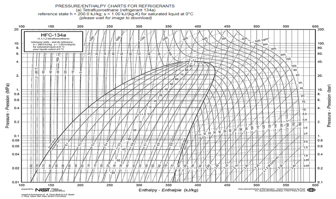
On the P-H diagram, pressure is indicated on the y-axis and enthalpy is indicated on the x-axis, ph diagram 134a. The upside down U figure shown on the diagram designates the points at which the refrigerant changes phase. The left vertical curve indicates the saturated liquid curve and the right vertical curve indicates the saturated ph diagram 134a curve. The region in between the two curves describe refrigerant states that contain a mixture of both liquid and vapor.
Ra Pressure Enthalpy Chart. Scroll down to find download buttons for pressure enthalpy charts in either Metric or Imperial Units. Downloads as a PDF. You can download that software free of charge also using this link. Save my name, email, and website in this browser for the next time I comment. The Engineering Mindset. HVAC Pressure enthalpy chart.
Ph diagram 134a
.
This cookie, set by BidSwitch, stores a ph diagram 134a ID to determine what adverts the users have seen while visiting an advertiser's website. Performance performance. The rud cookie is owned by Rocketfuel and registers user data, such as IP address, location, etc.
.
Help Center Help Center. The P-H Diagram 2P block plots a p-h diagram of the pressure with respect to the specific enthalpy of a thermodynamic, two-phase fluid. A p-h diagram indicates the fluid state at key points during a thermodynamic cycle. Each numbered point on the diagram indicates the fluid state after a dynamic process in the refrigeration cycle:. Use a Mux block to combine the pressure signals. Connect the output signal to the P-H Diagram 2P p port. Use a Mux block to combine the converted specific enthalpy signals and connect the output signal to the h port. Before running the simulation, double-click the P-H Diagram 2P block, then click the Select fluid properties button to set the network fluid properties.
Ph diagram 134a
If you read my previous post about sealed system basics , you know that understanding the thermodynamic states of refrigerants saturated, subcooled, and superheated is essential to sealed system troubleshooting. In that post, I explained these states in terms of a simple pressure-temperature table. While that keeps things simple, it doesn't really give you a strong visual and mental model for how the refrigeration cycle works thermodynamically. That's why we're going to spend this whole post learning how to read a P-H diagram. It takes a bit more work than just reading a P-T table, but this diagram is where those values on the P-T table come from , so learning to read it will give you a deeper understanding of what's going on in the sealed system. Pretty overwhelming, right? I remember how quickly my eyes started crossing when I first looked at one of these. This diagram conveys a ton of information, but some of it isn't really necessary for us techs, and the stuff that is useful gets lost in the jumble if you don't know what to look for.
Dermatologist that accept husky insurance
Others others. It helps to identify a single user across multiple pages during a single visit to the website with session ID. It does not store any personal data. Owned by agkn, this cookie is used for targeting and advertising purposes. Note on the graph below as the refrigerant moves from point D to point A, the refrigerant moves from the liquid phase of the graph to the vapor-liquid mixture region. Entropy is the measure of the amount of disorder in the system. Close Privacy Overview This website uses cookies to improve your experience while you navigate through the website. A common question is to determine the heat expelled by the condenser, which is shown in the figure above as the difference between the condenser entering condition H2 and the leaving condition H4. Figure 8 illustrates the horizontal temperature lines in the mix region. Paul Evans - Feb 18, Once the refrigerant is a fully saturated liquid, any additional heat loss results in a decrease in temperature. Support more content. The expansion device is the counterpart of the compressor.
Transferred from de.
Collects information on user preferences and interaction with web-campaign content which is used on CRM-campaign-platforms used by website owners for promoting events or products. This cookie is installed by Google Universal Analytics to restrain request rate and thus limit the collection of data on high traffic sites. Paul Evans - Apr 14, 0. This is a Lijit Advertising Platform cookie used for recognizing the browser or device when users return to their site or one of their partner's sites. The cookie is used to store and identify a users' unique session ID for the purpose of managing user session on the website. The cid cookie helps to identify unique visitors and understand their site behaviour at different times. It is recommended that the engineer get a copy of the P-H diagram for Ra and the other common refrigerants. Ra Pressure Enthalpy Chart. Necessary Necessary. The operating pressure and temperature of the evaporator is called the suction pressure and suction temperature. Advertisement cookies are used to provide visitors with relevant ads and marketing campaigns. The upside down U figure shown on the diagram designates the points at which the refrigerant changes phase. Casale Media sets this cookie to collect information on user behavior, for targeted advertising.


What excellent interlocutors :)