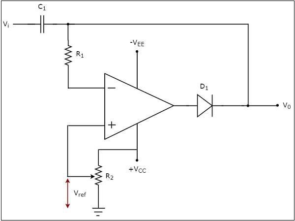
Precision op amp clamp circuit
Welcome, Guest.
Sp in ni ng Spark. This file contains additional information, probably added from the digital camera or scanner used to create or digitize it. If the file has been modified from its original state, some details may not fully reflect the modified file. Contents move to sidebar hide. File Talk.
Precision op amp clamp circuit
.
Sp in ni ng Spark.
.
Explore the intriguing world of voltage clamp circuits, their principle, components, and broad applications in electronics and neuroscience. The concept of voltage clamping is integral to the field of electronics and neuroscience. This article aims to provide a detailed and intuitive understanding of voltage clamp circuits, their workings, and their applications. Before we delve into the specifics, it is essential to grasp the fundamental concept. This is achieved by an external electronic circuit known as a voltage-clamp circuit. The core idea is to prevent the voltage across the device from going beyond a predetermined level, despite changes in the input voltage. The functionality of a voltage clamp circuit depends on its composition.
Precision op amp clamp circuit
An alternating current always changes its direction over time, but the direct current flows continuously in one direction. In a typical rectifier circuit, we use diodes to rectify AC to DC. But this rectification method can only be used if the input voltage to the circuit is greater than the forward voltage of the diode which is typically 0. We previously explained diode-based half-wave rectifier and full-wave rectifier circuit. To overcome this issue, the Precision Rectifier Circuit was introduced. The precision rectifier is another rectifier that converts AC to DC, but in a precision rectifier we use an op-amp to compensate for the voltage drop across the diode, that is why we are not losing the 0. So, in this tutorial, I am going to show you how you can build, test, apply, and debug a precision rectifier circuit using op-amp. Alongside that, I will be discussing some pros and cons of this circuit as well.
Taylormade m2 driver review
Quote from: Kleinstein on March 14, , am. Voltage regulator is the same "limiting" circuits as any clamp, only series instead of shunt. You're right, it doesn't work. It would add the delay of the buffer, but the OP-amp would one need to move by 2 diode voltages to engage the clamp. Also as far as I understand, it is generally considered a bad thing, a classic example of which is the explanation provided when giving an answer to "I have an unused op amp in the package, can I use it as comparator to avoid adding a dedicated comparator IC? It's up to you how to power up OP amp. This topic This board Entire forum Google Bing. Toggle limited content width. Read Edit View history. Pages: [ 1 ] Go Up. Hidden categories: Wikipedia images in SVG format All free media Wikipedia files on Wikimedia Commons for which a local copy has been requested to be kept. Quote from: Terry Bites on March 12, , pm.
Input-overvoltage-protected, low-power, low-noise four-channel op amp with super-beta inputs.
The function relies on the opamp going open loop. The version with comparator and switch should work OK when the input is low impedance. This image or media file may be available on the Wikimedia Commons as File:Precision op-amp clamp. Tools Tools. Voltage regulator is the same "limiting" circuits as any clamp, only series instead of shunt. Did you miss your activation email? While the license of this file may be compliant with the Wikimedia Commons, an editor has requested that the local copy be kept too. Low leak diode would be necessary. Kleinstein Super Contributor Posts: Country:. Contents move to sidebar hide.


Bravo, what necessary words..., a magnificent idea
Yes, really. So happens. We can communicate on this theme. Here or in PM.
Here so history!