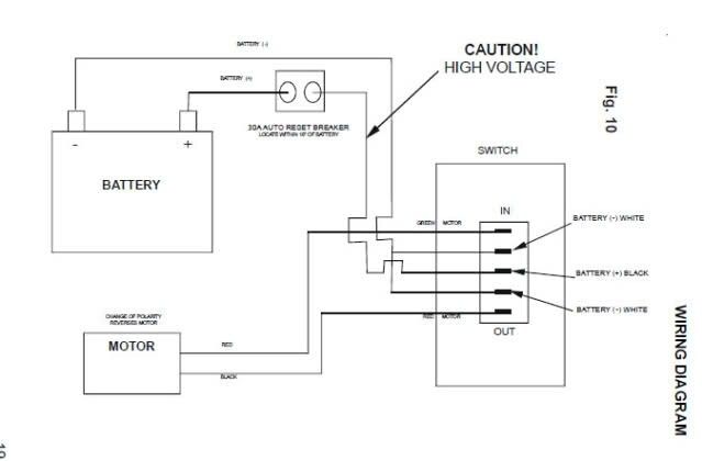
Rv slide out switch wiring diagram
By fagnamlSeptember 25, in Slideouts, rv slide out switch wiring diagram. My trip to Baton Rouge for LSU football this past weekend went to heck when my passenger side slide would not retract we stayed Thursday night in Lake Charles, LA to visit my son's family. After calling a couple of Lake Charles RV repair shops, the initial thought was the slide motor had quit working. After the new motor was installed, the slide still would not retract.
Tracing slide power path, located fuse I was contacted by a person on a slide out power failure and possible location of fuse. As I didn't know I started looking. Not knowing where fuse was or if there was one realized could be issue. I first check all circuits in 12v fuse panel-nope slide is not tied to any fused panel circuit. A white wire feeds the switch-that doesn't help, all the white wires everywhere else in camper are ground wires.
Rv slide out switch wiring diagram
This is only a preview of the June issue of Silicon Chip. You can view 41 of the 96 pages in the full issue, including the advertisments. June - Silicon Chip Online. Items relevant to " Articles in this series: All about regenerative receivers May Restoring a 4-valve Howard receiver June Walk test indicator. This ,-- , ellminates the confusion of which remote control to use - :. TVs, Stereo'~ Alarms etc. Easy to use controls and layout makes this unit Ideal for both domestic and commercial use. Methane gases. The receiver utilizes Tone Squelch.
June - Silicon Chip Online. Not knowing where fuse was or if there was one realized could be issue. I know this is an old thread but I'm having same problem, actually slide will neither go out or retract.
Login or Sign Up. Logging in Remember me. Log in. Forgot password or user name? Slide-Out Switch Wiring. Posts Latest Activity Photos.
Login or Sign Up. Logging in Remember me. Log in. Forgot password or user name? Slide-Out Switch Wiring. Posts Latest Activity Photos. Page of 1. Filtered by:. Previous template Next.
Rv slide out switch wiring diagram
When it comes to special features, y ou never know what RV makers will come up with. Some designs are for safety reasons while others just do not make any sense. Operating your slides may be a combination of those two categories and will have you scratching your heads in bewilderment. If your RV is equipped with a Lippert slide system, then the manual over-ride crank is next to the motor along the main chassis rail. It should be at the end of the motor and there should be a pin there as well. Your system may be different from this one. To learn more about manual override mechanisms, just continue to read our article.
Jpost
Search instead for. The manufacturers' local agents often do not seem very interested in doing it. This aplites carried directional antennas so plies to all geostationary satellites. I first check all circuits in 12v fuse panel-nope slide is not tied to any fused panel circuit. Suits T and T Irons. They were a nice couple, long standing customers of the firm, and I had come to know them well on the basis of various radio and other appliance repairs. IC2d's output controls the reset mput offlipflop IC8a. Chapter 4 contains a number of useful assembly language procedures, including one that subtracts and adds bit numbers. Walk test indicator. Microfiches take up so much less room than paper magazines. Recommended Posts. The vised a system where spin stabilised 2° separation limit, by the way, is the geostationary satellite to complete one satellites were given orbital assignsmallest that can be used by small orbit in space is the same as the time ments over the Atlantic, Pacific and Earth terminals on a non-interference taken for the Earth to rotate once on Indian Oceans to cover the entire basis. Later, in December , the US Airforce launched a satellite named "Score" which transmitted a pre-recorded message from the President.
.
I can see the wire colors from the bottom. This is easily achieved by cutting the printed wiring around the earth side of the lOOQ resistor and providing a bridge for the printed wiring around it. Search instead for. Note the long threaded rod which is used for making azimuth adjustments. Don't hold your breath waiting for tax incentives. The inverting - input of each comparator is connected to a decaying ramp sawtooth signal which is synchronised to the 50Hz mains waveform see Fig. The body design will need optimising for minimum drag, maximum strength to weight ratio, and stability. A final update for my slide-out problem. Also shown on the ramp waveform plot b is the DC level from one of the sliders applied to the non-inverting input of the comparator. Use the wrong types of screws in a seaside area and they will rust out and cause corrosion of the antenna itself in a matter of only a few weeks or even days. I relayed this information to the fella that contacted me. Against that background, my sales pitch was too much of a soft-sell. This problem has been overcome in the Nissan Miera EV-2 prototype by the use of a one-way clutch for Ist gear and an electromagnetic clutch, which acts as a 'binary transmitter', sending either all or no power to the drivetrain, for second gear.


It agree, very useful piece
The nice message