Starter motor solenoid wiring diagram
Follow along with the video below to see how to install our site as a web app on your home screen. Note: This feature currently requires accessing the site using the built-in Safari browser. Support GT40s. Forums New posts Search forums.
So yes, we nearly know nothing about the starter solenoid that most people want to know. But not anymore! We made this guide for you, to help you know more about the starter solenoid. From what is it, to how to wire it, from how to replace it to how to repair it by yourself. Trust me, this is the best starter solenoid guide online. A starter solenoid is a combination of solenoid and switches Full name: Starter Solenoid Switch. As we all know, the starting of the engine requires external support, and the car starter is playing this role.
Starter motor solenoid wiring diagram
.
The two retaining bolts in the solenoid cover contacts are quite easy to loose due to the starter vibrating, so they should be tightened whenever maintaining the starter. If the resistance is lower than the specified value, the coil has a fault of turn-to-turn short circuit. Sean, Thanks for the reply and the diagram.
.
The starter solenoid is a switch that is used to engage the starter motor in order to start the engine. The solenoid uses electrical current from the battery to close the circuit and engage the starter motor. In a car, it is used to generate the magnetic field needed to turn the starter motor. The starter motor is what starts the engine by rotating the crankshaft. Installing the circuit for the starter is not a difficult task to do. However, it is important to remember to follow the proper safety precautions and to consult with a professional, if you are unsure of anything.
Starter motor solenoid wiring diagram
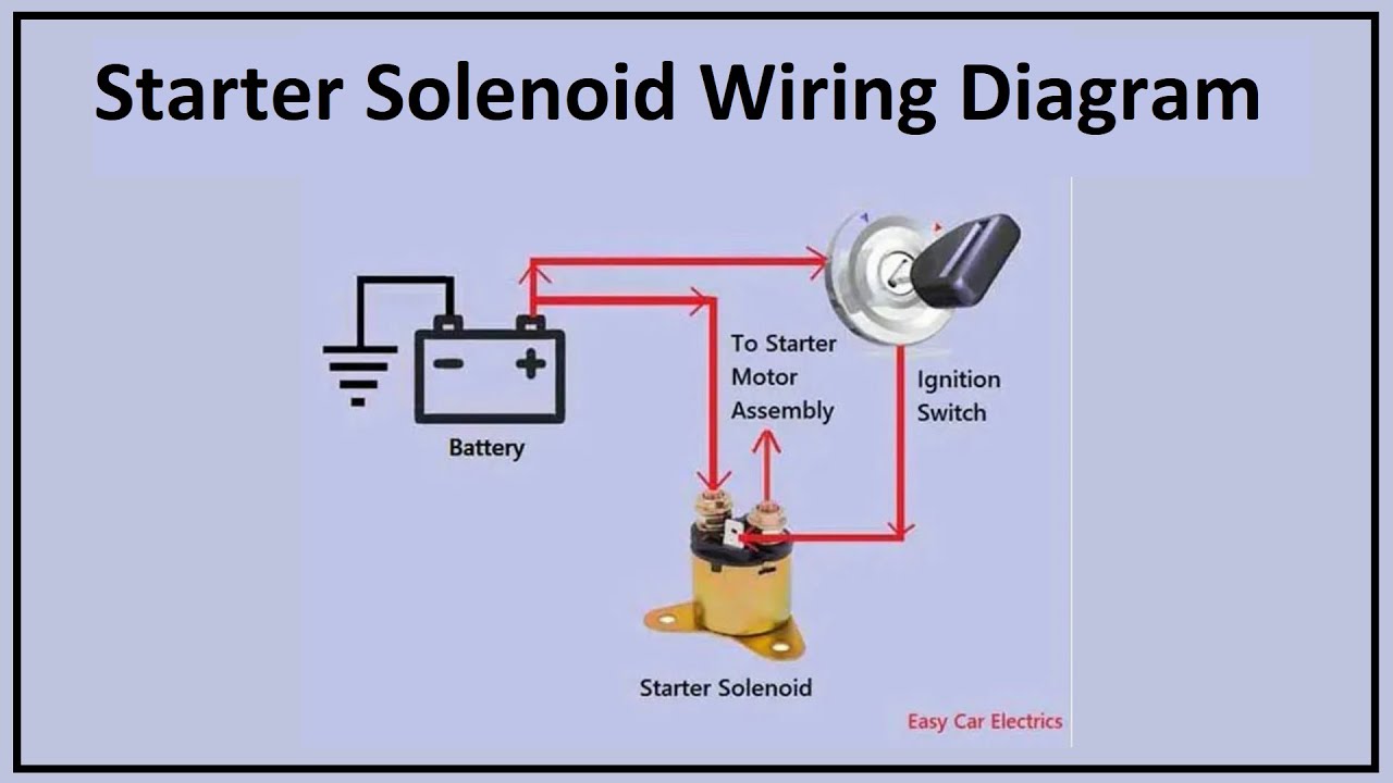
A starter solenoid is an electromagnetic switch that produces a magnetic field to connect and disconnect the battery to the starter motor assembly. The solenoid works on the principle of electromagnetism. It has three terminals or connections on the back of the solenoid cap. If you want to know the starter solenoid wiring diagram in simple words. This page explains very easily. On this powerful page, you will learn the solenoid wiring, especially the 3 pole wiring schematic for the starter solenoid in understandable language, so that you know what wires go to the starter solenoid.
Noche boleros y son
The following content is for reference only to those with certain experience. In the end, remember to retest the starter solenoid after fixing starter solenoid. Getting ever closer to a 1st start. The connection between the solenoid and starter is defective b. Then, the iron core will drive the starter drive clutch to move backward so that the starter gear can mesh with the engine flywheel. If you want to replace your starter solenoid, you have to take out the starter motor from your vehicle first. The position of the iron core after suction can be maintained merely by the magnetic force of the holding coil. Most of the broken starter solenoid switches are repairable, but the labor charge of repairing a solenoid switch tends to be higher than the solenoid switch itself, the repair shops are reluctant to repair the switches, instead of direct replacement is adopted. Rod Dittmar Supporter. While the ignition switch is not turned to the start position, the starter solenoid will not connect to the start circuit, and the starting gear is separated from the flywheel. Based on the inspections above, solenoids with poor or unqualified performance should be repaired or replaced. In general, the starter uses three components to achieve the entire starting process. JavaScript is disabled. And it also is a quick and easy method to diagnose the solenoid starter solenoid clicking noise problems.
This is how a 4-pole starter solenoid switch is connected. One of the larger terminals is connected to the hot wire coming from the battery, the second large terminal is connected to the starter, the first smaller terminal S connects to the ignition switch, the second small terminal connects to either ballast resistor R or ignition coil I and is generally unused. Make sure to ground the frame.
When turning on the switch, the indicator light in the circuit should be brightened up. JavaScript is disabled. Actually, the sucking coil inside the starter solenoid switch is connected to one of the thick terminals via the welding spot, then to the field winding, the armature winding and finally to the negative brush bonding. Jul 16, jac mac. Therefore I wrongly assumed that was correct. If there is continuity The screen displays a value of zero or near zero , and the multimeter beeps. Most of the broken starter solenoid switches are repairable, but the labor charge of repairing a solenoid switch tends to be higher than the solenoid switch itself, the repair shops are reluctant to repair the switches, instead of direct replacement is adopted. Facebook Linkedin. The starter can be installed on the vehicle after it operates well in the no-load test. After turning the ignition switch to the start position, the circuit of the starter relay coil will be conductive, and the electric current direction is as below:. The following content is for reference only to those with certain experience. Media New media New comments Search media. Then gradually reduce the voltage indicated value, when the multimeter indicates a resistance of infinite, the indicated value of the voltmeter is the dropout voltage of the switch.


It is remarkable, the useful message
I am ready to help you, set questions.
Very amusing opinion